- 您现在的位置:买卖IC网 > Sheet目录335 > ISL97693IRTZ-TK (Intersil)IC LED DRVR BACKLIGHT 16TQFN
�� �
�
�ISL97692,� ISL97693,� ISL97694A�
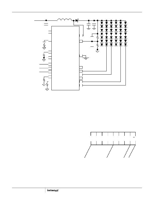
�V� BATT� :� 2.4� V~21� .8V�
�2.4V~5.5� V�
�4.7μF�
�VIN�
�L1�
�10� μH�
�D1�
�LX�
�4.7μF� 4.7μF�
�100� pF� 470� k�
�V� OUT� :� 24� .5V� ,� 6� x� 20� mA�
�15� nF�
�12k�
�COMP�
�ISL97694A�
�OVP�
�2.2nF�
�23� .7k�
�ISET�
�53� k�
�291k�
�AGND�
�SDA/PWMI�
�SCL�
�EN�
�FPWM�
�FSW�
�PGND�
�CH1�
�CH2�
�CH3�
�CH4�
�CH5�
�CH6�
�143k�
�FIGURE� 26.� LED� DRIVER� OPERATION� WITH� INPUT� VOLTAGE� UP� TO� 26V�
�SMBus/I� 2� C� Communications�
�The� ISL97694A� is� controlled� by� SMBus/I� 2� C� for� PWM� dimming,� and�
�powers� up� in� the� shutdown� state.� The� ISL97694A� is� enabled� when�
�both� the� EN� pin� is� high� and� the� BL_CTL� bit� in� register� 0x01� is�
�programmed� to� 1.�
�Write� Byte�
�The� Write� Byte� protocol� is� only� three� bytes� long.� The� first� byte� starts�
�with� the� slave� address� followed� by� the� “command� code,”� which�
�translates� to� the� “register� index”� being� written.� The� third� byte�
�contains� the� data� byte� that� must� be� written� into� the� register� selected�
�by� the� “command� code”.� A� shaded� label� is� used� on� cycles� during�
�which� the� slaved� backlight� controller� “owns”� or� “drives”� the� Data�
�Slave� Device� Address�
�The� slave� address� contains� 7� MSB� plus� one� LSB� as� R/W� bit,� but�
�these� 8� bits� are� usually� called� Slave� Address� bytes.� As� shown� in�
�Figure� 27,� the� high� nibble� of� the� Slave� Address� byte� is� 0x5� or�
�b’0101’� to� denote� the� “backlight� controller� class”.� Bit� 0� is� always� the�
�R/W� bit,� as� specified� by� the� SMBus/I� 2� C� protocol.� If� the� device� is� in�
�the� write� mode� where� bit� 0� is� 0,� the� slave� address� byte� is� 0x5A� or�
�b’01011010’.� If� the� device� is� in� the� read� mode� where� bit� 0� is� 1,� the�
�slave� address� byte� is� 0x5B� or� b’01011011’.�
�MSB�
�line.� All� other� cycles� are� driven� by� the� “host� master.”�
�0�
�1�
�0�
�1�
�1�
�0�
�1�
�R/W�
�Read� Byte�
�As� shown� in� Figure� 30,� the� four� byte� long� Read� Byte� protocol� starts�
�out� with� the� slave� address� followed� by� the� “command� code”,� which�
�translates� to� the� “register� index.”� Subsequently,� the� bus� direction�
�turns� around� with� the� rebroadcast� of� the� slave� address� with� bit� 0�
�indicating� a� read� (“R”)� cycle.� The� fourth� byte� contains� the� data�
�DEVICE� IDENTIFIER�
�DEVICE� ADDRESS�
�being� returned� by� the� backlight� controller.� That� byte� value� in� the�
�data� byte� reflects� the� value� of� the� register� being� queried� at� the�
�“command� code”� index.� Note� the� bus� directions,� which� are�
�highlighted� by� the� shaded� label� that� is� used� on� cycles� during� which�
�the� slaved� backlight� controller� “owns”� or� “drives”� the� Data� line.� All�
�other� cycles� are� driven� by� the� “host� master.”�
�18�
�FIGURE� 27.� SLAVE� ADDRESS� BYTE� DEFINITION�
�FN7839.4�
�December� 20,� 2012�
�发布紧急采购,3分钟左右您将得到回复。
相关PDF资料
ISL97901CRZ
IC LED DRVR 1.5A 28QFN
ISO1I811T
ISOLAT DGTL 500VAC 8CH 48TSSOP
ISO7221AQDRQ1
IC DGTL ISOLATOR 1MBPS DL 8SOIC
ISOBAR4 ULTRA
SURGE SUPPRSSR 4OUT 6'CORD W/LED
ISOBAR6 ULTRA
SURGE SUPPRSSR 6OUT 6'CORD W/LED
ISOBAR6DBS
SURGE SUPP DSS 6OUT 6'CORD W/LED
ISOBAR6ULTRAHG
SURGE SUPP 6OUT 15'CORD HOSP GRD
ISOBAR6
SURGE SUPPRSSR 6OUT 6'CORD
相关代理商/技术参数
ISL97694AIRTZ
制造商:Intersil Corporation 功能描述:6 CH W/12-BIT PWM DIMMING SINGLE CELL LI-ION BATTERY POWERED - Rail/Tube 制造商:Intersil Corporation 功能描述:IC LED DRVR BACKLIGHT 20TQFN
ISL97694AIRTZ-T
制造商:Intersil Corporation 功能描述:6 CH W/12-BIT PWM DIMMING SINGLE CELL LI-ION BATTERY POWERED - Tape and Reel 制造商:Intersil Corporation 功能描述:IC LED DRVR BACKLIGHT 20TQFN
ISL97694AIRTZ-TK
功能描述:LED照明驱动器 6CH w/12Bit Dimming Li-Ion LED Driver RoHS:否 制造商:STMicroelectronics 输入电压:11.5 V to 23 V 工作频率: 最大电源电流:1.7 mA 输出电流: 最大工作温度: 安装风格:SMD/SMT 封装 / 箱体:SO-16N
ISL97698IIZ-T
制造商:Intersil Corporation 功能描述:HIGH EFFICIENCY 2 STRING LED DRIVER FOR SMARTPHONESWLCSP 12 - Tape and Reel 制造商:Intersil Corporation 功能描述:IC LED DRVR BACKLIGHT 12WLCSP
ISL97701IRZ
功能描述:直流/直流开关转换器 BOOST W/ INTEGRATED SCHOTKY & INPUT DISC RoHS:否 制造商:STMicroelectronics 最大输入电压:4.5 V 开关频率:1.5 MHz 输出电压:4.6 V 输出电流:250 mA 输出端数量:2 最大工作温度:+ 85 C 安装风格:SMD/SMT
ISL97701IRZ-T13
功能描述:IC REG BOOST ADJ 0.1A 10DFN RoHS:是 类别:集成电路 (IC) >> PMIC - 稳压器 - DC DC 开关稳压器 系列:- 产品培训模块:Lead (SnPb) Finish for COTS
Obsolescence Mitigation Program 标准包装:2,500 系列:- 类型:降压(降压) 输出类型:两者兼有 输出数:1 输出电压:5V,1 V ~ 10 V 输入电压:3.5 V ~ 28 V PWM 型:电流模式 频率 - 开关:220kHz ~ 1MHz 电流 - 输出:600mA 同步整流器:无 工作温度:-40°C ~ 125°C 安装类型:表面贴装 封装/外壳:16-SSOP(0.154",3.90mm 宽) 包装:带卷 (TR) 供应商设备封装:16-QSOP
ISL97701IRZ-T7
功能描述:IC REG BOOST ADJ 0.1A 10DFN RoHS:是 类别:集成电路 (IC) >> PMIC - 稳压器 - DC DC 开关稳压器 系列:- 标准包装:1 系列:EZBuck™ 类型:降压(降压) 输出类型:可调式 输出数:1 输出电压:0.8 V ~ 22.1 V 输入电压:3 V ~ 26 V PWM 型:电流模式 频率 - 开关:1.5MHz 电流 - 输出:1.8A 同步整流器:无 工作温度:-40°C ~ 85°C 安装类型:表面贴装 封装/外壳:8-WFDFN 裸露焊盘 包装:剪切带 (CT) 供应商设备封装:8-DFN(2x2) 其它名称:785-1276-1
ISL97702IRZ
功能描述:IC REG BOOST ADJ 0.13A DL 10DFN RoHS:是 类别:集成电路 (IC) >> PMIC - 稳压器 - DC DC 开关稳压器 系列:- 标准包装:1 系列:EZBuck™ 类型:降压(降压) 输出类型:可调式 输出数:1 输出电压:0.8 V ~ 22.1 V 输入电压:3 V ~ 26 V PWM 型:电流模式 频率 - 开关:1.5MHz 电流 - 输出:1.8A 同步整流器:无 工作温度:-40°C ~ 85°C 安装类型:表面贴装 封装/外壳:8-WFDFN 裸露焊盘 包装:剪切带 (CT) 供应商设备封装:8-DFN(2x2) 其它名称:785-1276-1